Engine Layout and Firing Order
The nominal engine dimensions are: bore 68mm stroke 102mm giving a capacity of 1482cc.
The cylinders are usually numbered from 1 at the bulkhead end to 4 at the flywheel end, because Alvis viewed this engine as having been "turned round" in the chassis. By the same reasoning, the crankshaft turns clockwise when viewed from the rear of the car. The camshaft also turns clockwise, but the accessory drives turn anti-clockwise, (all viewed from the rear).
The firing order is 1 - 2 - 4 - 3
Valve clearances and engine timing
Valve clearances: 0.006" inlet and 0.012" exhaust (p.16 of Instruction Manual).
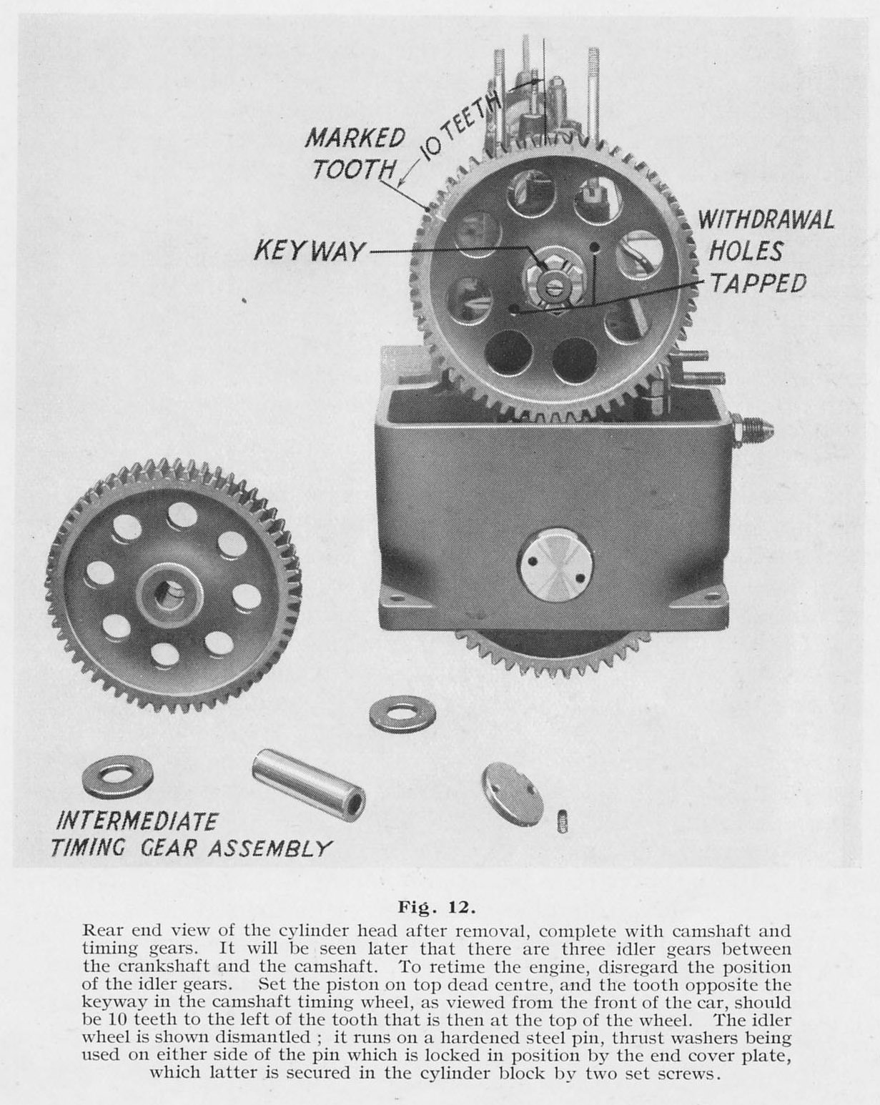
The valve timing adjustment is very simple and is described in Figure 12 of the Instruction Manual. The inlet and exhaust valve overlap is approximately centralised about top dead centre (TDC), so it is easy to check that the valve timing is correct by examining the cams for No.1 and No.4 cylinders, when at TDC on the 1 & 4 pistons. If there has been any error, it must be by one whole gear tooth, and is therefore completely obvious.
Ignition timing
There is an inspection plug in the top of the clutch pit, between the dynamo and the magneto. This allows sight of the timing marks on the edge of the clutch pressure plate. There are timing marks at TDC stamped 1 & 4 and at BDC stamped 2 & 3, and there is an unstamped ignition timing line at 38.6° before TDC on 1 & 4. In case you want to check any of this, the diameter of the clutch pressure plate is 320mm so 10° of crankshaft rotation corresponds to 27.9mm on the circumference.
There is one valve-related timing mark. This is at 10° AFTER top dead centre and is stamped "IN OP". Disregard this, as it appears to have been mis-stamped on at least some engines. It is never necessary to use this mark.
Timing the magneto is most easily done by the following procedure:
1) If your engine has been running, the adjustment must be approximately right and it may therefore help to mark all three parts of the vernier coupling before splitting it. Remove the magneto distributor cap. Loosen the magneto mountings so that the vernier coupling can be altered, but leave the nuts in place to retain the magneto loosely on its mounting flange.
2) Remove the clutch pit inspection plug and the spark plug from No.1 cylinder. To see into the inspection hole, it may help to remove the bonnet entirely.
3) Jack up the offside front wheel until the tyre is off the ground.
4) Select top gear.
5) Adjust the manual advance/retard control to the fully advanced position.
6) Set up a lamp or buzzer in circuit with the contact breaker on the magneto, so that the point of contact breaker opening can be observed.
7) Rotate the engine by rotating the front wheel in the forwards direction and determine the compression stroke on No.1 using a thumb over the spark plug hole to detect pressure.
8) Find the TDC mark for 1 & 4 and then rotate the engine backwards until the ignition timing mark appears in the centre of the inspection hole.
9) Check that the distributor rotor arm is pointing to the No.1 HT terminal. If the timing has not previously been set, then turn the magneto until the contact breaker is just opening, and set the fibre/rubber component of the vernier coupling in place while tightening the magneto mounting enough to hold it in position.
10) Rock the engine back and forth using the road wheel, and observe where the timing mark is, relative to the inspection hole, when the contact breaker opens, while rotating the engine forwards (so that all play in the magneto drive is taken up in the normal running direction).
11) Adjust the vernier coupling as necessary until the contact breaker is opening just as the timing mark passes the centre of the inspection hole. It is not necessary to tighten the magneto mounting fully for each trial, it is enough to just nip the vernier up. The engine can be nudged round very precisely using the road wheel. The fine adjustment on the vernier coupling is slightly better than 1° on the crankshaft, i.e. about 2.5mm on the timing mark position, so it should be possible to get the timing mark aligned within about 1 or 2mm of the target.
11) Tighten up the magneto fully, check the compression stroke and advance/retard position and re-test.
The above method is very precise and, on the FWD Alvis, it should result in reliable starting and good top end power.